Gxl1200 Microphone Wiring Diagram
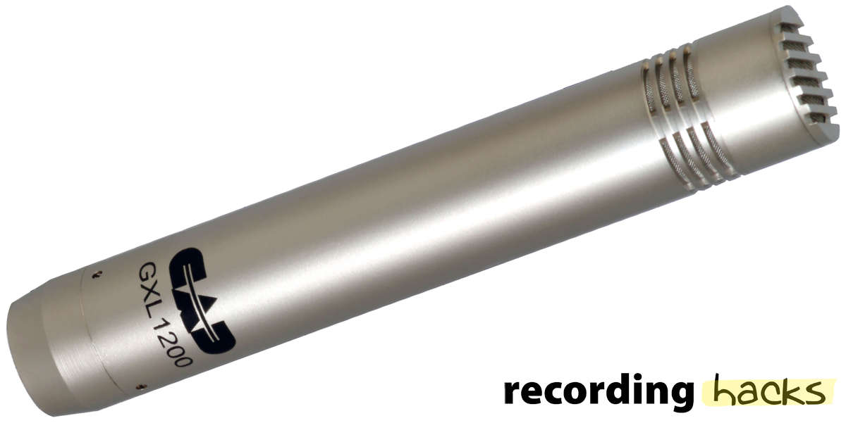
Cad Audio Gxl1200 Recordinghacks Com

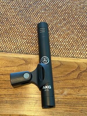
Akg Ck91 High Performance Cardioid Condenser Microphone Capsule

Rotary Switch Wiring Diagram Telecaster Mod Garage How To Wire A

Phantom Power Microphone Wiring And Circuit Diagram
Time Between The Notes Project Naiant Littlekit

Cad Audio Gxl2200 Studio Pack Gxl Condenser Microphone Kit Full

Cb secrets mike wiring wiring.
Gxl1200 microphone wiring diagram. And there are times when it s hard to figure out each wire s function and a color. The cb and microphone are too far from the desk causing a great deal of inconvenience. Microphone wiring color codes. Yes microphone wiring is so stressful when the right wiring info is out of reach.
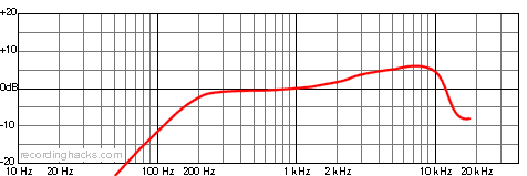
The gxl1200 s size accurate sound reproduction and high spl capability make this a great choice for miking overheads high hats cymbals woodwinds and stringed instruments. Gxl1200 microphone wiring diagram ide to usb service manual diagrams dishwasher wiring ge gsd530x. Cybernet chassis amstrad 900 901. 2001 ford f 150 fuse box diagram manual 2001 chevy s10 rear lights wiring harness diagram lucent avaya phone repair manual.
Mic wiring can be frustrating enough but when you can t find the right wiring info it is just impossible. I would like to create a splitter for the microphone so that i can use two 2 microphones the cb and original hand held microphone would remain where they are and the new microphone an a static desk top model would have a longer cord and be placed on the. Alba cb m1. Radio mic wiring diagram.
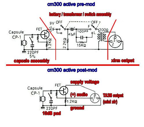
We will continue to try to get all the information that we can listed on this page. Please note i have drawn the capacitor with the wrong polarity marker. Watch my other video for a more up to date video using an. The chart and image above are correct for these models.
Astatic does not assume the responsibility of any damage to either the microphone nor any radio that has been modified to the specifications within this manual. Do better than cb radio. Although all have been known to work the wirings in this manual are only recommendations by astatic. Switch wiring inside the microphone.
The transformerless design of this instrument microphone allows it to have low distortion and optimum low end frequency response. Binatone 5 star route 66. Basic headlight wiring diagram tail light truck and four. What s better than cb.
The side should be connected to the resistor before the battery. Diagram 7 diagram 8 diagram 9.
Cad Audio Gxl2200 Large Diaphragm Condenser Microphone
Diy At8538 At8533 Or Similar Power Modules

From The Desk Of Dantone Wac Wiley Audio Corporation 2016
Mics Simmer Eq Freq Archive Cockos Incorporated Forums
Blown Up Something Using A Pad On A Battery Box M10 Sony Ecm 88
Http Cadaudio Com Images Uploads Cad Audio 2017 Catalog Pdf

Sony Xplod Cdx Gt540ui Wiring Harness Diagram Wiring Diagram
Microphones Condenser Microphone Excellent

Discover The Advantage Pdf Free Download

Cad Audio Gxl2200sp Scarlett 2i2 3rd Gen Samson Media One Bt3

We Know How To Work A Room Pdf Free Download

Taylor Dunn B150 Wiring Diagram Wiring Diagram
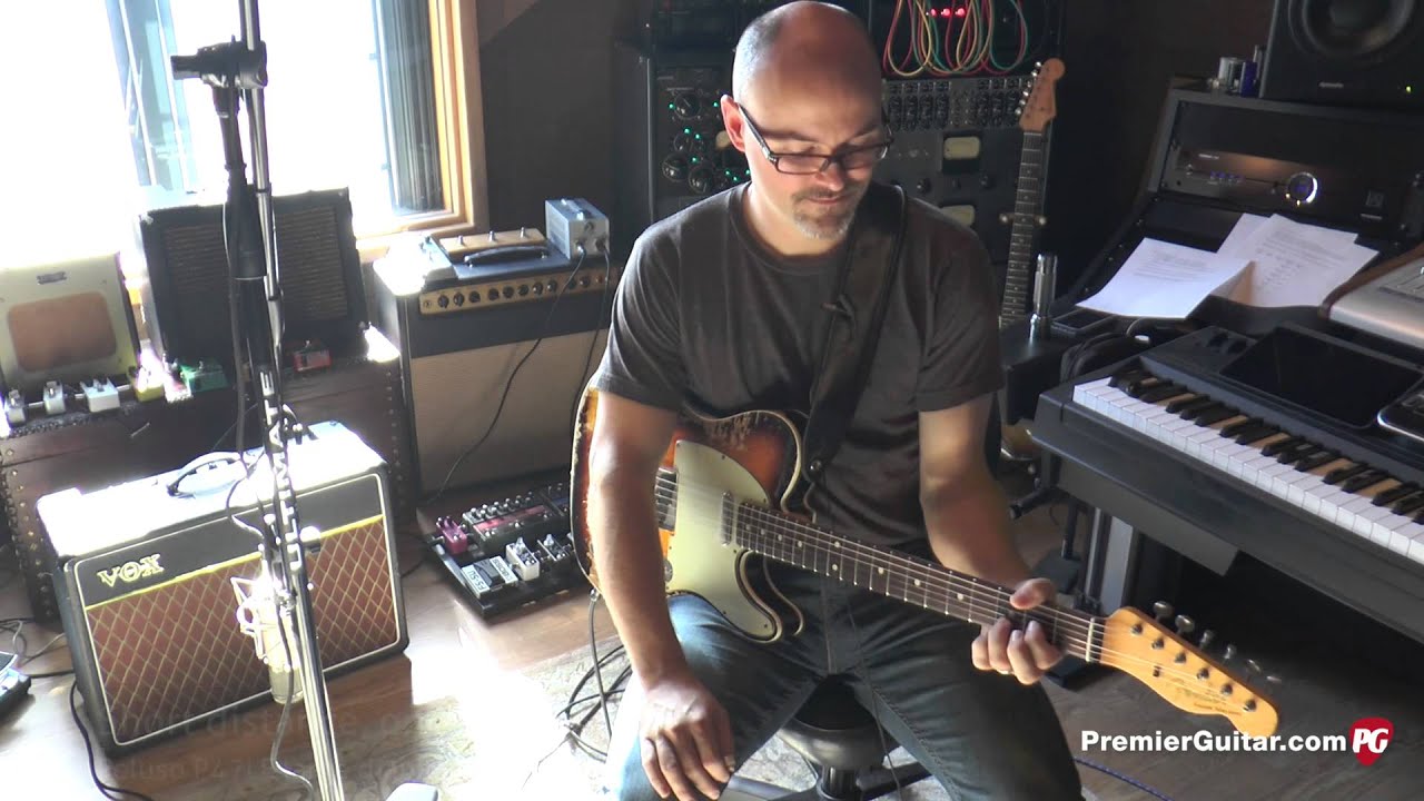
Diy How To Mic Your Amp For Stellar Tone Youtube
